Friday, August 5, 2022

Kedu Jd3 Switch Wiring Diagram

In fact the image in the pdf is labeled the exact same name as my switch. Kedu drill switch with nvr kjd12 10 amp.


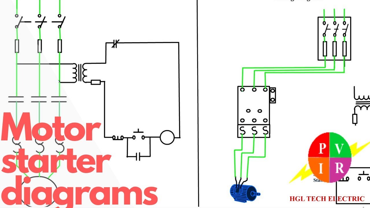
Motor Starter diagram. Start stop 3 wire control. Starting a three phase motor. YouTube

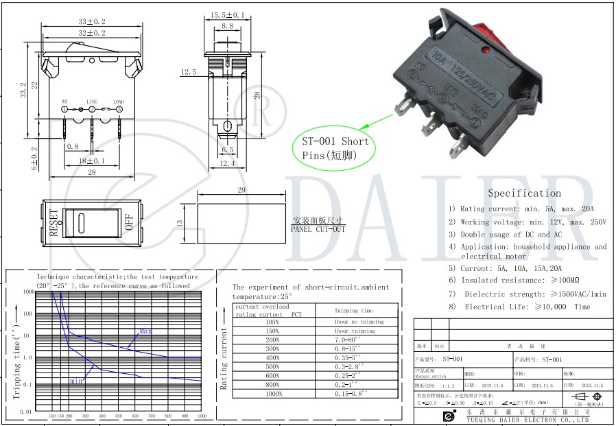
Disabling & locking switch the switch can be disabled and locked by inserting a padlock through the on/start button, as shown.

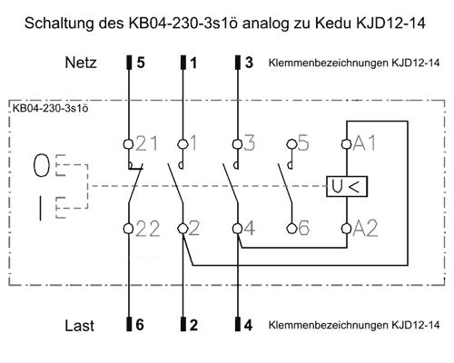
Kedu jd3 switch wiring diagram. Two on the line side and two on the load side. It has 7 terminals and can be used on any 3 phase (415volt) machinery up to 13.5 amps. (including postage) kedu jd3 230v 10pin switch relay for electric power tool undervoltage protection.

Limited time sale easy return. The item you've selected wasn't added to your cart. 6 days ago howhit cc wiring diagram along with howhit engine along with howhit wiring furthermore howhit cc carburetor.

Our problem was to establish if we had a line resistance from the fan relay to the thermo switch or an intermittent earth connection. The ecm gets data from the thermo switch and that is a 5 volt circuit. Howhit 150cc wiring diagram to properly read a wiring diagram one provides to learn how the components in the system operate.

Kedu factory supply with good price german plug and socket 16a 250v with vde,semko approved. Kedu jd3 switch wiring diagram. I rewired by using the wires from the old switch.

Two button start/stop switch with dust proof shield and emergency stop cover. Check out as a guest. Two button start/stop switch with dust proof shield and emergency stop cover.

Part of lamberts bikes online library of pdf motorcycle wiring diagrams. The switch is often used mounted into an additional cover plate. Electrical equipment complying with standards and matching.

According to earlier the traces in. The kedu kjd17b switch is widely used on woodworking machinery. Best products about electromagnetic switch , emergency stop switch and industrial plug and socket.

Sorry, we have detected unusual traffic from your network. The red button makes the green button pop up a bit. If the brakes work and doesn't blow the fuse, make the new wire permanent and route the wire properly.

The screws on the back are exactly like the pdf i linked. Sign up for mates rates. Sent from and sold by gangting electrical.

We managed to locate a circuit diagram off the web and discovered that the fan relay is controlled by the ecm. Suitable for machines with up to 2200w (2hp) 240v motors. Dl028 specific features label open switch switch closed rear view powered by tcpdf (www.tcpdf.org) 04/02/2022 7:14 pm specifications and prices are subject to change without notification page 1 of 1.

Please slide to verify help help Kedu hot sale waterproof danish socket 16a 250v ip54. Usually dispatched within 4 to 5 days.

Contact us for pricing and availability. Download and print the gxspiderbox for help with electrical troubleshooting. Kedu hy56 rear view of switch hot out hot in machine out 120v neutral or 230v hot in 120v neutral or 230v hot verified ground* power source figure 2.

Drill switch with nvr kjd12 10 amp. 03.11.2018 03.11.2018 6 comments on kedu switch wiring diagram. Australia's leading supplier of engineering, metal & wood working machinery.

Locking the switch in this It is either a 15amp 120 or a 10amp 240 (or something close to that). Sign in to check out.

I don't have wiring diagram for your model year. Leave pigtail at both ends, splice in new wire, you could let new wire just lay on the ground, for testing, from brake switch to rear brakes. 5 pole ignition switch wiring diagram.

The kedu kjd18/3 switch is widely used on 3 phase machines. Cheap switches, buy quality lights & lighting directly from china suppliers:kedu jd3 230/400v 16/12a electromagnetic switch on off emergency stop pushbutton switches for industrial machine tool equipment enjoy free shipping worldwide! Got new one but terminals are different.

Dimensions of black mounting plate 86mm x 55mm depth behind mounting plate 40mm Wiring nvr switch i have just bought an nvr switch unit from axminster power tool centre for my myford but theres no wiring diagram. How to use a wiring diagram.


Wiring diagram from Ign switch to fuse


DL028 31 SWITCH ON/OFF KEDU JD3 Hare & Forbes Machineryhouse


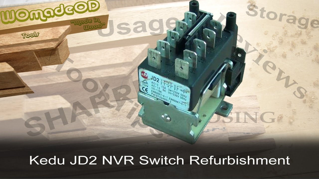
KEDU JD2 NoVolt Release Switch A Quick Refurb YouTube


Kedu Switch Wiring Diagram En 609471


table saw switch by recycle1943 woodworking community


Need help with final wiring procedure. Power supply to starter is in. Motor leads are


Kedu Switch Wiring Diagram En 609471


Wiring Diagram Outlets Light switch wiring, 3 way switch wiring, Outlet wiring


Need wiring diagram for accessory position on ignition key switch GM Square Body 1973 1987


3way switch wiring diagram with power in and switched leg in the same box NC Woodworker


Wiring Diagram 3 Way Switch New 3 Way Smart Switches Wiring Diagram New Ge Z Wave 3 Way Switch


3 Way Switch Electrical DIY Chatroom Home Improvement Forum


Kedu KJD1214 ein möglicher Ersatz von Klinger&Born


Video on how to wire a three way switch


Pin on Cabin Howto's


Kedu Jd32 110v 230v 400v 16a Relay For Switch Buy 16a Relay,16a Relays,230v Relay Product on


20 Unique 3 Pin Toggle Switch Wiring Diagram


DIY Speaker Switch AVS Forum Home Theater Discussions And Reviews


110 vac Grizzly Vertical Milling Machines G0728 User Manual Page 42 / 60

Thursday, August 4, 2022

Define Pcb In Os

Pcbs were manufactured domestically from 1929 until manufacturing was. The inner softer core part of a.


Circuit Board Builder define pcb in os

Parc científic de barcelona (spanish:

Define pcb in os. Data structuring for processes is. The pcb related to the process is also stored in the queue of the same state. Pcbs are used in both desktop and laptop computers.

Refer to § 761.1(b) for applicable concentrations of pcbs. Os provides a virtual machine: They serve as the foundation for many internal computer.

If the process is moved from one state to another state then its pcb is also unlinked from the corresponding queue and added to the other state queue in which the transition is made. Pcb and pcbs means any chemical substance that is limited to the biphenyl molecule that has been chlorinated to varying degrees or any combination of substances which contains such substance. If operating system not store the compulsory information about the process in process control block, then os is unable to manage and handle the.

A pcb is a thin board made of fiberglass, composite epoxy, or other laminate material. • also usually want to abstract away from grungy harware, i.e. Process control block is used for storing the collection of information about the processes and this is also called as the data structure which stores the information about the process.

The pcb call schedules a psb for your program to use. Peoples community bank (virginia) pcb: Computer engineering mca operating system.

Threads and its types in operating system; For this task, the process control block (pcb) is used to track the process's execution status. Pcbs, or polychlorinated biphenyls, are industrial products or chemicals.

Process table and process control block (pcb) interrupts; Pcb and pcbs as contained in pcb items are defined in § 761.3. When pcb is not developed, at that time all components are connected with a wire which increases complexity and decreases reliability of.

Pcb is a data structure in the os and it contains all the information about a process. Panama city beach (florida) pcb: Thus, the pcb is the data structure that defines a process to the operating systems.

You can use separate i/o areas for each segment type, or you can define one i/o area that you use for all segments. Operating system questions and their answers dr. Kernel and shell of os.

Each block of memory contains information about the process state, program counter, stack pointer, status of opened files, scheduling algorithms, etc. Share physical resources between them. Pcb contamination is high in the housatonic river and new bedford harbor in massachusetts.

The address of the dliuib parameter returns the. The pcb is a certain store that allows the operating systems to locate key information about a process. Why os uses pcb for each process?

Conductive pathways are etched or printed onto board, connecting different components on the pcb, such as transistors, resistors, and integrated circuits. Difference between process and thread Operating system, process, process state, pcb, dispatcher, dispatch latency,

The various information which is stored into the pcb as followings: Qasim mohammed hussein page 1 q1: The information of the process is used by the cpu at the run time.

Context switching involves storing the context or state of a process so that it can be reloaded when required and execution can be resumed from the same point as earlier. This is a feature of a multitasking operating system and allows a single cpu to be shared by multiple processes. The role or work of process control block (pcb) in process management is that it can access or modified by most os utilities including those are involved with memory, scheduling, and input / output resource access.it can be said that the set of the process control blocks give the information of the current state of the operating system.

Full form of pcb in operating systems is the process control block. Partido comunista brasileiro (brazilian communist party) Operating system functions • regardless of structure, os needs to securely multiplex resources:

A process is an active entity ripe for execution (must have a The operating system manages various types of queues for each of the process states. Protect applications from each other, yet 2.

One pcb layout is defined in the linkage section.


Eagle Pcb Software Download PCB


Circuit Board Builder define pcb in os


enjoy discount price and free shipping Graphics Card, Half


Pcb Diagram In Operating System Circuit Board Builder


How to design the LCD circuitry


EBC Professores da UFMS inventam chip de computador mais


Circuit Board Builder pcb definition in os


PPT Integration Relation for Control Volume PowerPoint


Circuitos de comparação com IC 741, IC 311, IC 339 Axtudo


Pcb Diagram In Operating System Circuit Board Builder


Resource Allocation Graph In Operating System


inter process communicat how do programs communicate


Circuit Board Builder define pcb in os


Circuit Board Builder Define Pcb In Os


PPT Microkernels, virtualization, exokernels PowerPoint


enjoy discount price and free shipping Graphics Card, Half


"The LittleKnown Open Source OS That Rules the


PCB de Ipatinga realiza convenção e define candidaturas


Como a Edge Computing está transformando o mundo Grupo

Lowrance Hds Wiring Diagram

Is there any chance you can provide one for the following. Diagram lowrance hds 7 wiring networking diagrams картплоттер 10 ais interfacing to gen2 3 5m installation manual pdf and cobra m57 touch structurescan point 1 not being recognized sonar diagram lowrance hds 7 wiring full version hd quality diagramaplay parcodellegite it lowrance help topics networking diagrams wiring картплоттер lowrance hds 10 ais форум.


R 485 Wiring Diagram

I am just a bit confused with the ehernet portion of it all.

Lowrance hds wiring diagram. March 4, 2011 at 2:21 am #1306790. A long press opens the find menu. Lowrance hds wiring diagram wiring diagram is a simplified conventional pictorial representation of an electrical circuit.

Gone trying to remove, replace or repair the wiring in an automobile, having an accurate and detailed lowrance hds 7 wiring. Before attempting to rewire a transducer connector you should. Senin, 13 desember 2021 reviewed in the united states on july 28, 2017.

The gen2 5 and 7 units have only 1 ethernet port, allowing a unit. Hereby navico holding as declares that this hds is in compliance. Lowrance hds 5m installation manual pdf help topics networking interfacing to elite 5 sonar structure scan wiring diagram and cobra m57 power cable for series transducer 7 pin adaptor nse 7x anciens et réunions lowrance hds 5m installation manual pdf manualslib lowrance help topics networking diagrams wiring interfacing to lowrance elite 5 sonar […]

It shows the components of the circuit as simplified shapes, and the capability and signal contacts with the devices. The manual does not cover basic background information about how equipment such as radars, sonar, and ais work. Lowrance hds 5m gps wiring diagram wiring diagram database.

Adjusting sensitivity and colorline sensitivity and colorline. Lowrance hds 16 carbon with structurescan 3d module and transducer. The lowrance hds range of multifunction displays is on its third generation and all units feature a single nmea0183 port that our wln10/wln30 can connect to.

Lowrance hds 7 wiring diagram tagged lowrance hds 7 gen 2 wiring diagram, lowrance hds 7 wiring diagram,at of wiring diagram lowrance nmea wire hds 7 fish finder 89 diagrams electrical for elite 4 schematic installing 5 chirp transducer c x hdi yellow nc 4x dsi ti hd with0lowrance hds 7 wiring diagram 5ace. Cable wiring diagram in your hds installation manual for more information. The port must output and input data at the same baud rate, so if you already have an ais connected to this port then you will need to reconfigure the wln10 baud rate to 38400 baud.

Lowrance hds gen 1 and 2 keypad models 5, 7, 8, and 10 sonar settings. Lowrance structurescan wiring diagram installation instructions for installing the lowrance structurescan hd processor module unit for a more panoramic view underwater. Important text that requires special attention from the reader is emphasized as follows:

Refer to the lowrance owners manual for operation. Wiring diagram for lowrance hds 7 full diagrams gen3 features specs 1990 structure scan 1969 simrad help support sonichub hook scania diagram wiring for lowrance hds 7 full version hd quality hassediagram picciblog it lowrance help topics networking diagrams wiring lowrance hds 7 wiring diagram lowrance hds 7 gen3 features specs comparisons […] From the thousands of pictures on the web concerning lowrance hds 7 wiring diagram, we picks the top libraries together with ideal image resolution only for you all, and now this photos is usually among images selections in your ideal photographs gallery in relation to lowrance hds 7 wiring diagram.i'm hoping you will like it.that impression (lowrance hds 7.

The diagram below shows how to connect the multiplexer between the lowrance chart plotter and the matrix ais vhf radio. After connections are made the lowrance chart plotter, the communications port must be configured to 38400 baud. I turn to page 26, and see the diagram showing the wiring fan out that identifies the.


Lowrance Elite 7 Hsd Wiring Diagram


Wiring Diagram For Lowrance Elite 5 Hdi


Lowrance Hds 12 Wiring Diagram Wiring Diagram


Lowrance HDS Wiring Question The Hull Truth Boating


Lowrance Elite 5 Hdi Wiring Diagram Drivenheisenberg


Lowrance Hds 7 Wiring Diagram


Lowrance Hds 7 Wiring Diagram


Lowrance Hds 7 Wiring Diagram Lowrance Wiring


Lowrance Wiring Harness Wiring Diagram Schemas


Lowrance Hds 7 Live Wiring Diagram Wiring Diagram


Lowrance LBS1(Broadband sonar) question about 3


Multiple HDS9 gen2touch HELP The Hull Truth Boating


Lowrance Hds 12 Wiring Diagram Wiring Diagram


Lowrance Hds 7 Wiring Diagram


20 Images Lowrance Elite 5 Wiring Diagram


47+ Wiring Diagram For Lowrance Hds 7 PNG Kunne Diagram


Lowrance Elite 5 Hdi Wiring Diagram


Lowrance Hds 12 Wiring Diagram Wiring Diagram


Lowrance Elite 7 Hsd Wiring Diagram

Featured Post

93 Camry Wiring Diagram

Detroit Ddec 4 Ecm Wiring Diagram, How to start a Series 60 Detroit Swap Mawk wiring 12.7 14L DDEC IV, 3.78 MB, 02:45, 32,122, Bob Brenner,...

Popular Post